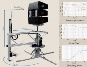
The Klippel Near Field Scanner (NFS) revolutionizes the art of loudspeaker measurement.
Measurement of the spherical radiation of a sound source can be made in 1° increments producing incredibly accurate radiation balloons and in a “typical” room-not an anechoic chamber. By measuring the sound source in the near field, room reflections can be separated from direct sound. Holographic processing algorithms developed by Klippel then convert the near-field measurements and reflections into a far field response. The results can be viewed as 3D radiation balloons, horizontal and vertical polar plots at any user-defined frequency. This also allows for full spectrum SPL measurements at any point in space- and at any distance.
Near field measurements have higher S/N and are less prone to reflection and air propagation effects. The scanning process can be performed in a non-anechoic environment through field separation where the outgoing wave (direct sound) is separated from the incoming waves (reflected sound).
The NFS is ideal for measuring the power response of large professional live performance speakers without the need for a huge chamber or the complication of precisely rotating a large and heavy speaker cabinet. The sound pressure in the near field can also be used to evaluate small studio monitors, tablets, laptops, and other personal audio devices.
Frustrated in getting your speaker to the consultant using EASE (Enhanced Acoustic Simulator for Engineers) on their projects? Warkwyn can insert your speaker’s acoustic data into the growing EASE speaker database as a benefit of Near Field Scanning; voila—done!
This is an incredibly powerful analytical and predictive tool that can save weeks of inefficient trial and error design work. Another way that Warkwyn can save you precious time and expense.
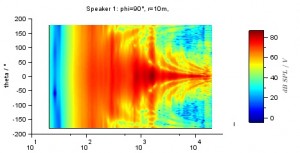
Line array contour plot 10m.
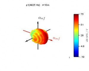
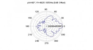
Line array directivity balloon 5kHz 10m
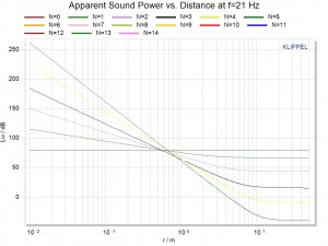
Sound power vs. distance at f=21 Hz. This graph shows how the higher order coefficients contribute to the measurement. By definition, the apparent sound power in the far field is constant. This is the 1/r^2 law. The far field begins somewhere between 3x and 10x (Beranek) 50X (Fincham) the size of the speaker. In this diagram you can see that the sound power does not flatten out until past 10m. That needs a big chamber for a free field measurement. As a result, most anechoic chamber loudspeaker measurements are not actually made in the far field. Click to enlarge.
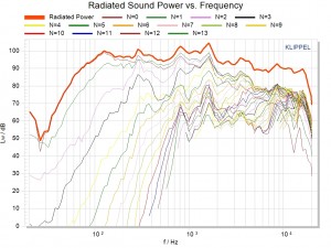
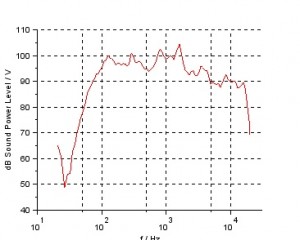
Line array radiated sound power vs. frequency. This graph shows that most of the low frequency data comes from the first few coefficients, but that high frequencies require more coefficients, and hence more measurements. Click to enlarge.
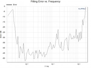
Fitting error shows the frequency range where the data is valid, and how valid it is. Any error < -20dB is acceptable. With NFS, You can run measurement samples until an acceptably small error is achieved. In anechoic chamber measurements, there is no mechanism to measure the error; and the chamber specifications are only valid within very specific regions of the chamber. Click to enlarge.
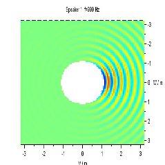
Line array wave propagation 1kHz horizontal plane.
